Find our
products online

Find our
products online
KWIK Anchoring system provides design calculations for anchors conforming to European Technical Assessment (ETA) ensuring safe anchoring in concrete or masonry by evaluating characteristic resistance values under specific load conditions, usually following EN 1992-4 or EOTA Technical Reports (e.g., TR 029, TR 023). Calculations, performed by in-house experienced engineers verify safety againstfailure modes such as pull-out, steel failure, or concrete cone breakage.
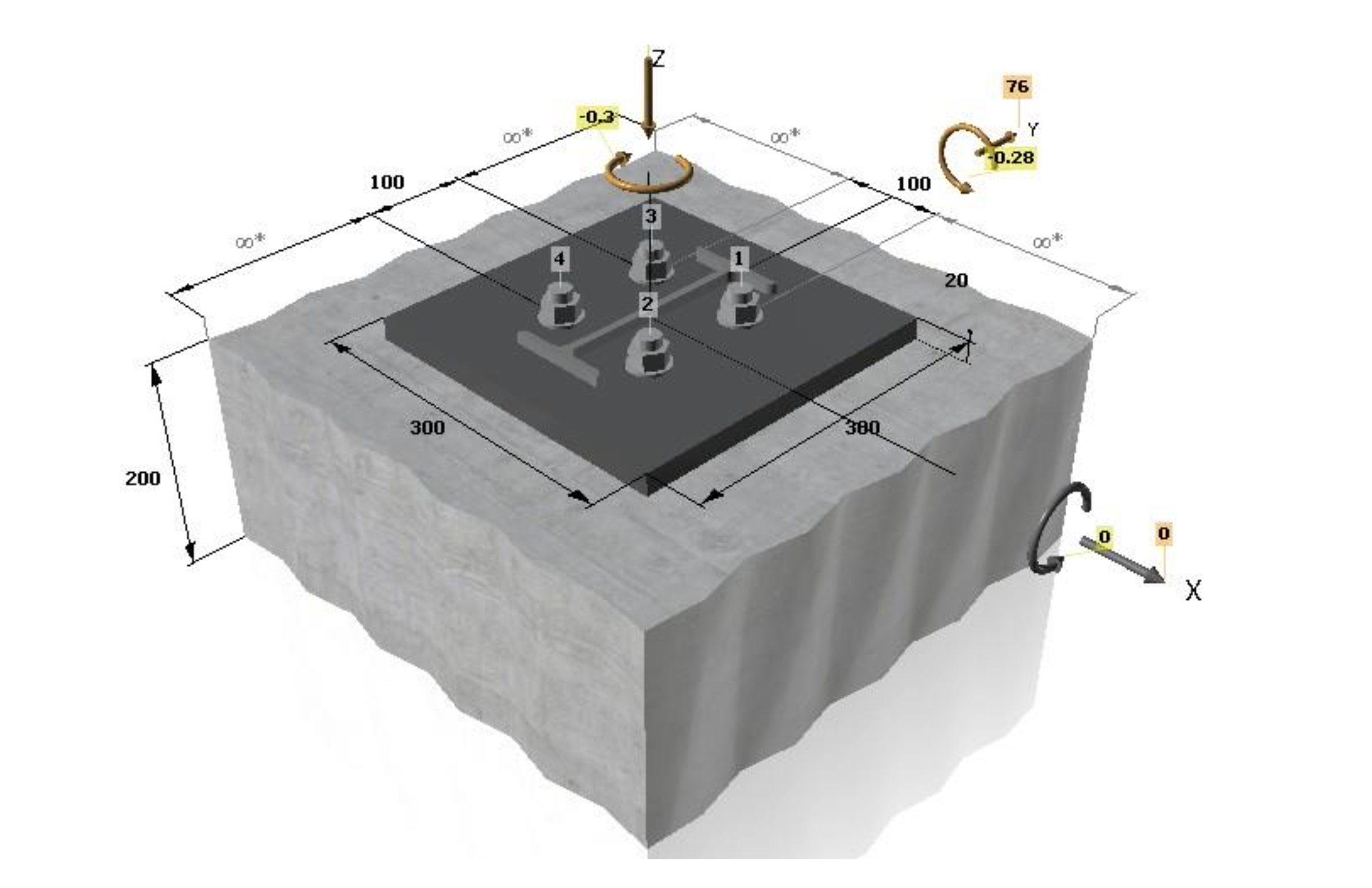
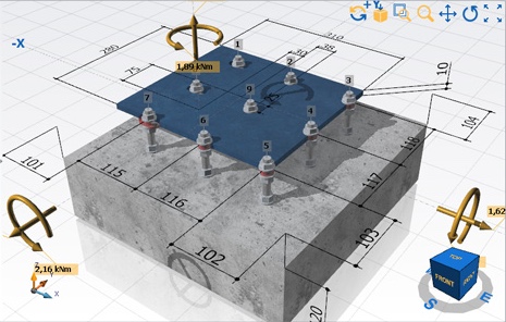
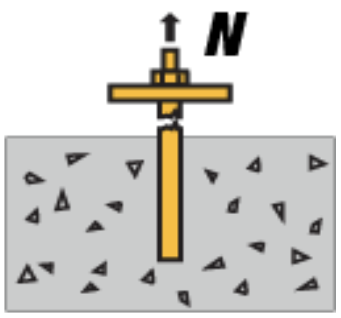
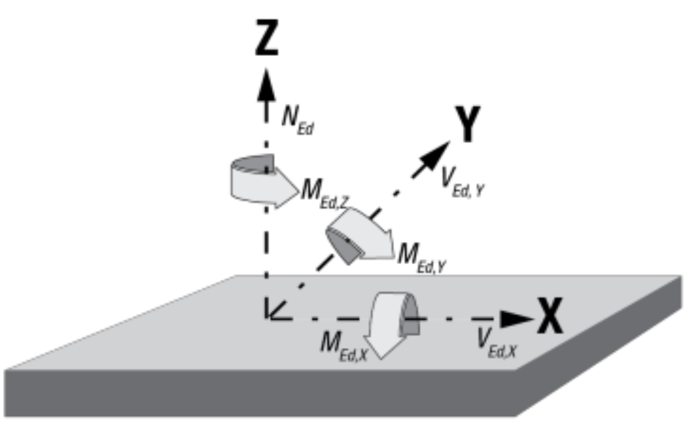
Identify Loading: Determine axial tension (𝑁𝑆𝑑), shear (𝑉𝑆𝑑), and bending moments acting on the anchor group.
Determine Concrete Strength: Define the characteristic compressive strength (𝑓𝑐𝑘,𝑐𝑢𝑏𝑒 or 𝑓𝑐𝑘,𝑐𝑦𝑙).
Define Geometry: Establish edge distances (𝑐), spacing between anchors (𝑠), and member thickness (ℎ).
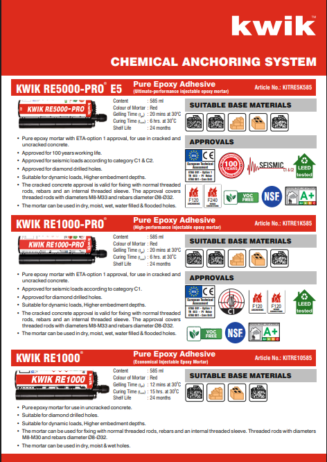
Select Anchor Product: Select anchor type, diameter (𝑑), and effective embedment depth (ℎ𝑒𝑓) from the European Technical Approval (ETA)
Tension resistance must be checked for four failure modes, with the lowest value determining the design resistance (𝑁𝑅𝑑):
Steel Failure: Calculate 𝑁𝑅𝑑,𝑠 = 𝑁𝑅𝑘,𝑠 / 𝛾𝑀𝑠
Combined Pullout and Concrete Cone Failure: Calculate 𝑁𝑅𝑑,𝑝 = 𝑁𝑅𝑘,𝑝 / 𝛾𝑀𝑝, considering characteristic bond strength, embedment depth, and group effects (spacing/edge distance modifiers).
Concrete Breakout Failure: Calculate 𝑁𝑅𝑑,𝑐 = 𝑁𝑅𝑘,𝑐 / 𝛾𝑀𝑐, focusing on the projected area of the concrete cone.
Splitting Failure: Check for splitting, especially if edge distances are small, calculate 𝑁𝑅𝑑,𝑠𝑝 = 𝑁𝑅𝑘,𝑠
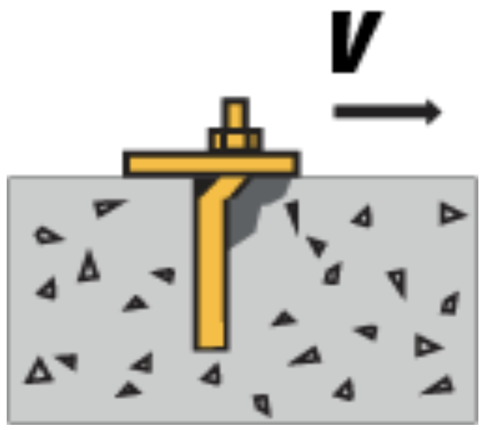
Shear resistance must be checked for three failure modes, with the lowest value determining the design resistance (𝑉𝑅𝑑):
Steel Failure: Calculate 𝑉𝑅𝑑,𝑠 = 𝑉𝑅𝑘,𝑠 / 𝛾𝑀𝑠, both with and without a lever arm.
Concrete Pryout Failure: Calculate 𝑉𝑅𝑑,𝑐𝑝 = 𝑘 x 𝑁𝑅𝑑,𝑝 (or 𝑁𝑅𝑑,𝑐), where 𝑘 is a factor from the ETA.
Concrete Edge Failure: Calculate 𝑉𝑅𝑑,𝑐 based on shear direction, edge distance, and concrete breakout at the edge.
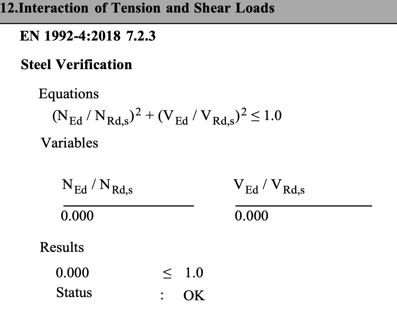
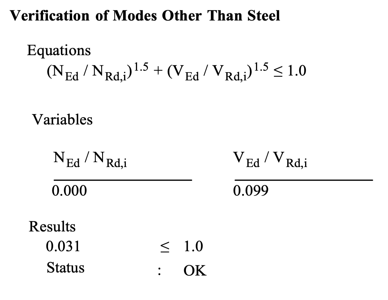
If both tension and shear are present, the interaction must be verified.
A common interaction formula is: 𝛽𝛼𝑁 + 𝛽𝛼𝑉 ≤ 1.0
Where 𝛽𝑁 = 𝑁𝑆𝑑 / 𝑁𝑅𝑑 (tension utilization) and 𝛽𝑉 = 𝑉𝑆𝑑 / 𝑉𝑅𝑑 (shear utilization).
Typically, 𝛼 = 1.5, but it can range from 1.0 to 2.0 depending on failure modes
Check Displacements: Verify that expected displacements at design load levels are within allowable limits.
Installation Data: Check that minimum edge distances and spacing conform to the ETA.
Check Condition A/B: Verify if supplementary reinforcement is present (Condition A) or absent (Condition B) to select appropriate partial safety factors (𝛾𝑀𝑐)
Steel: 𝛾𝑀𝑠 (varies by steel grade).
Concrete: 𝛾𝑀𝑐 = 1.5 (usually, can vary with safety class).
Bond: 𝛾𝑀𝑝 (depends on concrete type/installation conditions).
Note: For official design, the specific European Technical Approval (ETA) for the chosen anchor product must be used in conjunction with EOTA TR 029.